


Views: 0 Author: Site Editor Publish Time: 2026-09-23 Origin: Site


Engineers and product designers frequently face a difficult balancing act during product development. You want a perfectly dimensioned part, but pushing for extreme precision everywhere can quickly derail your project budget. Specifying unnecessarily tight injection molding tolerances exponentially increases tooling costs, extends lead times, and drives up manufacturing scrap rates. We must acknowledge the unpredictable realities of plastic behavior. Thermoplastics shrink, warp, and shift during the cooling process. This makes them fundamentally different from the stable metals used in standard CNC machining. This article will guide product designers and procurement teams in defining functional, manufacturing-friendly tolerances. You will learn how to effectively balance high-end precision with everyday commercial viability. We will explore material constraints, essential tooling strategies, and accepted industry standards to optimize your next production run.
Every product development team wants perfectly dimensioned components. However, extreme precision comes at a steep premium. You must weigh the financial cost against the actual functional need of the part. Understanding the baseline difference in expectations is vital for project success.
Commercial tolerances generally target ±0.005 inches per inch. They focus on maintaining standard cycle times and lower tooling costs. They also ensure a highly acceptable functional yield for most consumer goods. You can easily achieve these dimensions using standard processing techniques. Conversely, fine or precision tolerances push limits down to ±0.002 inches per inch. These tighter dimensions require high-class tooling, such as SPI Class 101 molds. Manufacturers must also implement meticulous temperature control systems and conduct frequent metrology inspections during production.
The cost multiplier for precision is massive. Moving from a standard baseline to a fine tolerance can easily double or triple your mold costs. Tighter machining simply takes much longer. Multi-cavity balancing becomes a complex engineering headache. You will also need intensive mold iterations to dial in the final dimensions perfectly.
Yield implications matter greatly in this equation. Overly strict dimensional callouts inevitably lead to higher rejection rates in quality control. QC teams will flag and discard more parts. The buyer ultimately pays for these wasted materials, lost machine hours, and reduced output.
Commercial vs. Precision Molding Characteristics
| Characteristic | Commercial Tolerances | Fine / Precision Tolerances |
|---|---|---|
| Typical Range | ±0.005 in/in | ±0.002 in/in |
| Tooling Class | SPI Class 103 or 102 | SPI Class 101 |
| Cost Impact | Baseline standard | 2x to 3x higher |
| Inspection Needs | Standard AQL sampling | Frequent CMM measurement |
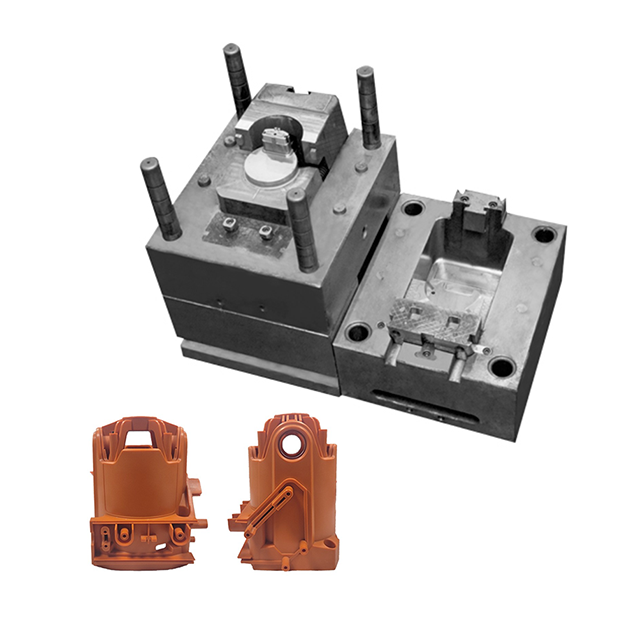
Many designers assume steel dictates the final part shape. The plastic resin actually plays a much larger role. Material shrinkage and flow characteristics are the heaviest limiters on precision.
We must contrast amorphous polymers with semi-crystalline polymers. Amorphous resins, like Polycarbonate (PC) and ABS, have predictable, uniform shrinkage. They shrink evenly in all directions as they cool. Semi-crystalline polymers, like Nylon and POM (Delrin), behave differently. They are prone to anisotropic shrinkage. This means they shrink at different rates depending on the flow direction. This uneven cooling routinely causes warpage, which destroys dimensional accuracy.
Glass fillers further complicate shrink rates. Adding glass fibers to a resin increases stiffness. It also restricts shrinkage along the direction of the fiber alignment. You must account for this directional behavior when designing a precision plastic injection mold.
Part geometry heavily influences cooling rates. Non-uniform wall thickness leads to differential cooling across the part. Thick sections take longer to solidify than thin sections. As the thick areas cool, they pull on the already solid thin areas. This internal stress causes warpage, directly defeating tight dimensional callouts.
Tooling quality is the final major variable. Manufacturers use a "steel safe" approach to dial in precision. They purposefully cut the mold cavity slightly smaller than required. A high-quality tool requires rigid, high-grade steel like H13. Strong steel prevents tool deflection under massive injection pressures, ensuring repeatable part dimensions over millions of cycles.
Engineers often mistakenly apply metal machining standards to plastic parts. Plastics require their own distinct dimensional frameworks. You should reference global standards designed specifically for molded polymers.
Standard frameworks like DIN 16901 or ISO 294-4 serve as excellent baseline references. These documents account for polymer behavior, moisture absorption, and thermal expansion. Relying on standard metal machining tolerances is a guaranteed path to production failure. Plastics simply move too much after leaving the mold.
We advocate strongly for using GD&T (Geometric Dimensioning and Tolerancing). Rigid linear dimensions across a large part are notoriously difficult to hold. GD&T allows you to control functional assembly requirements much better. For example, specifying flatness for a sealing face is far more useful than a strict thickness tolerance. Concentricity and true position controls ensure mating gears fit perfectly without over-constraining unrelated features.
The engineering drawing title block is a common trap. Many companies leave a default "±0.001" tolerance in their standard CAD templates. Applying this universal tight tolerance block to a plastic file is a primary driver of rejected quotes. It forces molders to over-engineer the tool for non-critical features, inflating part costs unnecessarily.
Smart engineering requires strategic dimensioning. You can lower costs and improve yields by following established Design for Manufacturability (DFM) rules. Focus your efforts only where they matter most.
Implementing these DFM strategies makes setting injection molding tolerances much more manageable. You protect your budget while securing the exact functionality your product demands.
Many vendors claim they can hit extremely tight tolerances. You must verify these claims before cutting expensive tooling steel. Evaluating a partner requires looking at their historical data and actual process controls.
First, demand real data rather than marketing promises. Instruct your purchasing buyers to ask for process capability indices. Request Cpk or Ppk reports from previous precision runs. A Cpk of 1.33 or higher proves they can consistently produce parts within your required limits. Without this data, you are simply guessing.
Next, carefully assess their process control methodologies. A capable vendor should use scientific molding principles. They need cavity pressure sensors to monitor the melt in real time. They must also utilize decoupled molding techniques. This isolates the high-speed filling phase from the packing phase. Decoupled molding drastically reduces part-to-part variation.
You also need to verify their advanced metrology capabilities. Check their quality control lab equipment. Do they use automated Coordinate Measuring Machines (CMM)? Do they have optical comparators or CT scanning technology? They must actually possess the equipment necessary to measure the precision they claim they can mold.
Finally, encourage your team to take the right next steps. Transition away from theoretical design limits. Engage in a formal DFM review and Moldflow analysis with your shortlisted vendor. This collaborative step aligns expectations before any metal is cut.
Specifying precise dimensions for plastic components requires careful thought. It is primarily an exercise in risk management and resource allocation, rather than simple CAD drafting. You must understand how polymers behave inside a heated steel tool to succeed.
Precision is absolutely achievable in plastics. However, it must be strategically applied to critical features to avoid wasting capital. Over-tolerancing drives up tooling budgets and ruins production yields. By embracing standard limits for non-functional areas, you protect your bottom line.
Now is the time to optimize your upcoming project. We prompt you to upload your CAD file for a technical DFM review. Our engineers will help you align your dimensional requirements with actual manufacturing realities, ensuring a smooth and profitable production launch.
A: Generally, manufacturers can achieve ±0.002 inches (±0.05 mm) for specialized applications. This requires highly stable resins, robust tooling, and single-cavity molds. Some advanced micro-molding processes can achieve even tighter dimensions. However, pushing for these limits is rarely recommended for standard commercial parts due to high costs.
A: Plastics behave entirely differently than metals. Polymers are subject to significant thermal expansion, varied shrink rates, and internal stresses during the cooling phase. CNC machining cuts stable, solid metal at room temperature. Applying metal standards to plastic guarantees high failure rates and rejected production batches.
A: Multi-cavity molds introduce more processing variables. Cavity-to-cavity variations occur due to different runner flow distances, pressure drops, and localized cooling differences across the mold base. Because of these variations, you generally need to specify slightly looser tolerances compared to a single-cavity prototype mold.
A: Steel safe means designing the initial mold cavity slightly undersized. As a result, the first molded plastic part comes out slightly larger or thicker than needed. If the dimension is out of tolerance, the toolmaker can easily remove metal from the mold to fix it, avoiding expensive welding.


