


Views: 0 Author: Site Editor Publish Time: 2026-08-13 Origin: Site


Transitioning from a functional 3D CAD model to a moldable part represents the highest-risk phase of hardware development. Injection molding requires significant upfront capital to begin. Flaws in your part preparation easily lead to severe tooling rework. These errors extend lead times and ruin unit economics before you even scale production. Preparing a part correctly requires precise alignment. You must strictly balance functional design requirements alongside material physics and tooling constraints. This comprehensive guide outlines the exact evaluation frameworks you need. We detail the proven manufacturability protocols necessary to de-risk your investment entirely before anyone cuts steel. By understanding these core principles, you gain much better control over your product launch timeline. You will learn how to bridge the gap between digital concepts and physical manufacturing realities smoothly. Proper preparation ensures long-term manufacturing success without burning through budgets.
CAD does not equal moldability: A valid 3D model often requires structural compromises (drafts, uniform walls) to survive the injection and ejection processes.
DFM prevents tooling delays: Executing rigorous DFM for injection molding early reduces tooling modifications, which are costly and delay time-to-market.
Material dictates mold design: Shrinkage rates and thermal properties of your chosen resin must be finalized before mold tooling begins.
Partner evaluation goes beyond cost: Choosing a manufacturer requires assessing their in-house DFM capabilities, tooling guarantees, and production scalability.
Engineers often rush rapidly from prototype to production. They assume a successful 3D print guarantees an easily moldable product. This assumption creates massive financial implications. Proper custom injection molding and plastic part design prevents this dangerous trap. Without modifying the initial design for tooling, you risk creating completely unmanufacturable components.
The "tooling rework" trap is particularly dangerous for hardware startups. Modifying an existing mold by removing steel is sometimes possible. For example, making a wall thicker means cutting away metal from the core. However, adding steel to a mold to fix a missing feature is exponentially more expensive. It often demands a complete rebuild of the entire cavity. You lose weeks or even months of progress. Your critical launch date slips.
To avoid this, we must define clear success criteria upfront. A successfully prepared part achieves a delicate and intentional balance. It maintains your required aesthetic qualities while ensuring robust mechanical integrity. More importantly, it facilitates the shortest possible cycle time during manufacturing. It accomplishes this without generating ugly cosmetic defects like sink marks or dimensional warping. You achieve scalable manufacturing only by prioritizing these specific factors early during the CAD phase.
Good design principles directly influence your final manufacturing outcomes. Implementing a strict evaluation framework prevents costly mistakes later. We must focus deeply on the non-negotiable geometric requirements. Robust DFM for injection molding bridges the gap between digital models and physical realities. A thorough review saves significant capital.
Here is a numbered list of core features-to-outcomes you must address before locking your design:
Uniform Wall Thickness: Thick sections cool much slower than thin ones. This uneven cooling causes the material to shrink unevenly across the part. It leads to ugly sink marks and severe dimensional warping. Maintain consistent thickness to ensure uniform cooling rates across the entire component. Coring out thick sections preserves strength while saving expensive material.
Draft Angles: Vertical walls sticking straight up will jam tightly inside the cavity. Drafts are absolutely essential for clean, damage-free ejection. Standard rules dictate a 1-2 degree minimum draft for standard parts. You must add additional degrees for textured surfaces. This practice prevents part scoring and heavily reduces premature mold wear over time.
Radiused Corners: Sharp interior corners create massive stress concentrations. They severely impede resin flow during the initial filling phase. Adding a generous radius allows molten plastic to flow smoothly around sharp bends. It also structurally strengthens the final component, preventing premature mechanical failures during stress tests.
Managing Undercuts: Undercuts trap the part inside the rigid steel cavity. They force you to use expensive side-actions, cams, or lifters inside the tool. Eliminate undercuts whenever possible to keep costs low. Redesigning snap fits or employing pass-through coring keeps your tooling budget highly manageable.
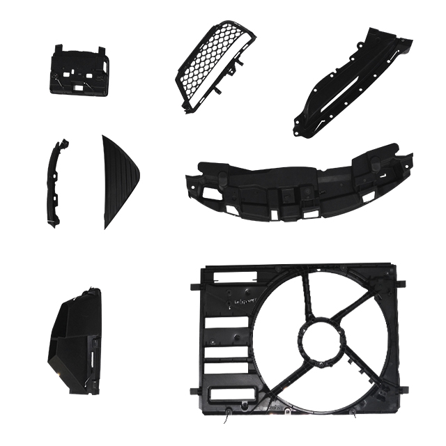
You cannot finalize a mold design without locking in your exact material first. The physics of your chosen resin dictate the physical reality of the tool itself. Choosing plastic is never an afterthought in hardware development.
Let us examine how material properties fundamentally influence injection mold tooling. As molten plastic cools, it inevitably shrinks. Different resins shrink at vastly different rates depending on their molecular structure. Semi-crystalline plastics like Nylon shrink much more than amorphous plastics like ABS. Engineers must size the steel cavity slightly larger to accommodate this exact calculation. If you change materials later, the part will instantly fall out of tolerance.
Flow characteristics also play a major role in tool design. We measure this attribute using the Melt Flow Index (MFI). Highly viscous materials struggle to fill complex geometries or thin walls. They require specialized gating strategies and larger runner systems. This careful design ensures the cavity fills completely before the plastic freezes off at the gate.
Finally, consider your post-processing constraints carefully. Some parts require secondary painting, electroplating, or ultrasonic welding. The base resin must chemically and mechanically support these specific secondary operations. If you choose a highly chemically resistant plastic, paints might not adhere properly. Select the material based entirely on the end-use environment and post-mold requirements.
Chart: Typical Shrinkage Rates by Material Family
Material Type | Typical Shrinkage Rate (in/in) | Flow Characteristic |
|---|---|---|
ABS | 0.004 - 0.008 | Good flow, highly stable dimensions |
Polycarbonate (PC) | 0.005 - 0.007 | High viscosity, requires hotter mold temperatures |
Nylon (PA66) Glass-Filled | 0.002 - 0.006 | Low shrinkage, fast freezing, high strength |
Polypropylene (PP) | 0.010 - 0.020 | High shrinkage, excellent flow, highly flexible |
Your tooling path depends heavily on your product lifecycle volume and initial budget. We break these solution categories into two distinct strategic paths. Choosing the wrong path wastes precious capital and extends your timeline.
Rapid or bridge tooling relies on softer metals like aluminum. It offers a significantly lower upfront cost and a much faster turnaround. Aluminum tools are ideal for rapid design validation and early market testing. They handle low-volume production runs typically ranging from 1,000 to 10,000 units. However, they degrade much faster than steel under extreme injection pressure. Aluminum tools cannot withstand abrasive resins like glass-filled nylon for very long.
Production tooling utilizes fully hardened steel. It requires a substantially higher initial capital expenditure and much longer lead times. Yet, it easily withstands millions of cycles without losing any dimensional accuracy. This extreme durability makes it absolutely essential for manufacturing high-volume OEM plastic parts. Steel tools allow for intricate multi-cavity designs to drastically reduce per-part cycle costs over time.
Risk mitigation remains highly crucial during this transition phase. We strongly recommend running a single-cavity prototype mold first whenever possible. You use this to validate your complex geometry, cosmetic finishes, and mechanical fit. Only after successfully proving out the single-cavity tool should you commit to an expensive multi-cavity production tool.
Comparison: Prototyping vs. Production Tooling
Feature Category | Bridge Tooling (Aluminum Molds) | Production Tooling (Hardened Steel Molds) |
|---|---|---|
Initial Capital Expenditure | Low to Moderate | High to Very High |
Average Lead Time | 2 - 4 Weeks | 6 - 12 Weeks |
Estimated Tool Life (Cycles) | 10,000 - 50,000 maximum | 1,000,000+ continuous |
Best Used For | Validation, beta testing, bridge production | Mass market scaling, high-volume consistency |
Shortlisting logic goes far beyond just checking the cheapest unit prices. You need a highly reliable vendor when you are ready to transition to full manufacturing. Evaluate potential partners meticulously based on their engineering transparency and technical infrastructure.
First, demand a highly transparent DFM analysis. A trustworthy partner proactively provides a comprehensive report before asking for any tooling deposit. This engineering report should thoroughly detail mold flow analysis, ideal gate placements, and exact ejector pin locations. If a vendor skips this critical step, they pose a massive risk to your timeline.
Second, strictly compare in-house tooling capabilities versus brokering. Many vendors secretly outsource their mold-making to third-party overseas shops. This brokering introduces huge communication delays into your project. It makes routine maintenance incredibly frustrating. In-house tooling offers vastly better accountability across the board. If a tool breaks down mid-run, an in-house team fixes it immediately on the shop floor.
Finally, mandate strict quality compliance and intellectual property security. Require clear documentation for material lot traceability. Request comprehensive First Article Inspection (FAI) reports for your initial production samples. Ensure the manufacturer employs highly secure data handling protocols for your proprietary CAD files. Protecting your intellectual property remains just as important as producing the physical product itself.
Preparing a plastic part for production is an exercise in strategic compromise. You must continuously balance ideal product geometry against the harsh physical realities of manufacturing. Every design decision heavily impacts your final launch timeline and overall budget.
Your immediate next step is to firmly finalize your material selection. Do this before making any further geometric changes to your model. Then, request a formal DFM review from a highly qualified manufacturing partner. Never lock in your final CAD without securing their expert engineering input.
Do not let minor design flaws derail your entire product launch. Submit your functional 3D model today for an expert DFM analysis and a comprehensive tooling quote. Securing this early feedback guarantees a much smoother transition into high-volume manufacturing.
A: Generally 1 to 2 degrees for untextured surfaces, adding 1.5 degrees for every 0.001 inches of surface texture depth.
A: Only if the new material has the exact same shrinkage rate as the original. Otherwise, the final part dimensions will fall out of tolerance.
A: Varies by complexity and material. Aluminum bridge tooling can take 2–4 weeks; multi-cavity hardened steel production molds typically require 6–12 weeks.
A: Thick sections cool slower than thin sections. This differential cooling causes the material to pull against itself, leading to surface depressions (sink marks) and physical warping.


