


Views: 0 Author: Site Editor Publish Time: 2026-09-01 Origin: Site


A vague Request for Quote (RFQ) is the leading cause of tooling rework, delayed launches, and budget overruns in high-stakes manufacturing. You simply cannot afford ambiguity at this stage. In the decision phase, relying on a vendor's subjective claim of "high quality" is a massive liability. A reliable precision injection mold requires rigorous mathematical definitions, standardized classifications, and rigid acceptance criteria. Subjective terms leave far too much room for manufacturing errors.
To mitigate financial risk and ensure functional success, buyers must transition from conceptual designs to an exhaustive, data-backed specification document before commissioning tooling. This means leaving nothing to interpretation. In this comprehensive guide, we will explore exactly how to define your tolerance limits, select appropriate steel grades, manage thermal dynamics, and validate the final build. You will learn the specific metrics needed to hold tooling partners accountable from day one.
Tolerance dictates cost: Specifying tight tolerance molding unnecessarily drives up tooling costs; tolerances must align strictly with functional fit and standard capabilities.
Classification matters: Defining mold lifespan via SPI standards (e.g., Class 101 vs. 103) ensures the tool steel matches production volume expectations.
Material drives design: Finalizing the exact resin grade upfront is non-negotiable due to unique shrink rates and thermal dynamics.
Validation requires data: A robust specification must outline First Article Inspection (FAI) and Process Capability (CpK/PpK) requirements to hold the injection mold manufacturer accountable.
Many buyers over-specify tolerances across the entire part. This habit leads to exorbitant quotes and unmanufacturable designs. Engineers often place blanket tolerances on a CAD drawing just to be safe. However, this approach backfires during the tooling phase. Machining every surface to extreme accuracy requires specialized equipment and drastically slower cutting speeds. You end up paying a premium for precision on surfaces where it offers zero functional benefit.
You must differentiate between standard commercial practices and true high-precision requirements. Standard commercial tolerances generally fall around ±0.005 inches. Most modern molding facilities can achieve this using standard equipment and basic climate controls. In contrast, high-precision tolerances often reach ±0.002 to ±0.001 inches or tighter. Achieving this level of accuracy requires specialized machining, strict environmental controls, and scientific molding principles. True tight tolerance molding demands highly capable CNC and EDM machines running in temperature-stabilized rooms.
We advise specifying ultra-tight tolerances only on critical dimensions. Conduct a rigorous cost-to-benefit reality check before submitting your RFQ. Focus your precision requirements on mating surfaces, gear teeth, fluid seals, and snap fits. Leave non-critical areas at standard commercial tolerances. This targeted approach balances part compliance with commercial viability. It ensures you only pay for precision where it actually matters.
Tolerance Capability Comparison Chart
Tolerance Level | Typical Range (Inches) | Manufacturing Impact | Ideal Application |
|---|---|---|---|
Standard Commercial | ±0.005 to ±0.010 | Fast machining, standard tool steel, lower cost. | Enclosures, non-mating surfaces, cosmetic covers. |
High-Precision | ±0.001 to ±0.002 | Slow EDM cutting, climate control required, premium steel. | Gears, fluid seals, medical devices, critical snap fits. |
Ultra-Precision | Sub ±0.001 | Scientific molding required, intense metrology, high rejection risk. | Micro-fluidics, advanced optics, aerospace connectors. |
Building a specification sheet requires breaking down structural and mechanical expectations. You must communicate these variables clearly to the tool builder. A robust specification eliminates assumptions. We recommend dividing your requirements into distinct solution categories. This ensures your custom mold tooling meets both immediate production needs and long-term durability expectations.
You must specify total expected life cycles upfront. The Society of Plastics Industry (SPI) classifications provide a universal language for this. For example, if you expect 1 million or more cycles, you must mandate an SPI Class 101 mold. If you only need 50,000 parts for a pilot run, a Class 103 or 104 mold is far more economical. Do not overbuild your tool if your volume projections are low.
Next, define your cavitation requirements based on annual volume targets. Decide whether you need a single-cavity, multi-cavity, or family mold. Multi-cavity molds increase upfront costs but drastically lower the piece-part price. Family molds can produce different components simultaneously, but they complicate material flow and process tuning. Make sure you align cavitation limits with your machine press tonnage availability.
SPI Mold Classification Guidelines
SPI Class | Expected Cycles | Tool Steel Hardness | Best For |
|---|---|---|---|
Class 101 | Over 1,000,000 | High (48-52 HRC) | High-volume continuous production. |
Class 102 | Up to 1,000,000 | Medium-High (45-48 HRC) | Medium-to-high volume runs. |
Class 103 | Under 500,000 | Medium (28-35 HRC) | Low-to-medium volume, less abrasive resins. |
Correlate resin abrasiveness and mold class directly to your tool steel selection. Glass-filled or mineral-filled polymers are highly abrasive. They will quickly erode soft steel. For high-volume abrasive resins, specify hardened steels like H-13 or S-7 on the Rockwell scale. If you are molding unfilled commodity plastics at lower volumes, P-20 steel is usually sufficient and much easier to machine.
You must also outline requirements for surface treatments or specialized plating. If you plan to mold corrosive resins like PVC or POM, the outgassing will degrade unprotected steel rapidly. Specify nickel or chrome plating for the core and cavity blocks. This prevents rust, extends mold life, and maintains the integrity of your textured surfaces.
Specify the gate type and location meticulously. The gate is where molten plastic enters the cavity. Its placement dictates how the material fills the part. Common options include hot runners, cold runners, edge gates, and submarine gates. Hot runner systems waste less material but cost significantly more to build and maintain. Gate placement must prevent cosmetic defects and manage shear stress effectively.
Ejection mechanics can easily ruin a perfectly molded part. Define acceptable ejector pin marks and parting line limits in your specification. Follow these best practices for ejection strategies:
Place ejector pins on non-cosmetic, hidden surfaces whenever possible.
Specify maximum allowable flash limits along the parting line (usually under 0.002 inches).
Require guided ejection systems if dealing with deep cores or delicate features.
Outline specific draft angles required to facilitate smooth part release.
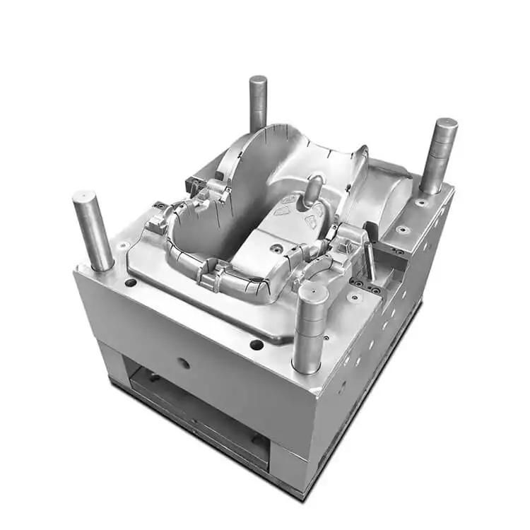
Implementation realities dictate how a tool is manufactured. Tooling dimensions are cut directly in response to a specific polymer's behavior. Steel is relatively unforgiving. Once a cavity is cut too large, fixing it requires welding and re-machining, which weakens the tool. Therefore, understanding material flow is the foundation of precision tooling.
Providing a generic material family is simply insufficient. Stating "Nylon" or "Polycarbonate" on an RFQ sets you up for failure. The specification must name the exact resin manufacturer and specific grade. A glass-filled nylon will shrink far less than an unfilled nylon. If the mold builder calculates shrinkage based on the wrong grade, your final parts will fail dimensional inspection immediately. You must finalize the exact resin grade upfront.
Thermal management is another critical variable. Plastics shrink as they cool. If a part cools unevenly, it will warp. For complex geometries, you should specify the requirement for conformal cooling channels. Unlike traditional straight-drilled water lines, conformal channels wrap around the contours of the part. This ensures uniform temperature distribution, which is critical to preventing warp in a complex industrial plastic mold. It speeds up cycle times and improves dimensional stability.
Require your vendor to establish a Design for Manufacturability (DfM) baseline. Make Moldflow or equivalent simulation software mandatory. These simulations predict how the plastic will enter the cavity, where weld lines will form, and where air traps might occur. Simulating the flow allows engineers to validate draft angles and predict sink marks before any steel is actually cut. It is a vital risk-mitigation step.
For heavily regulated sectors, the mold itself becomes part of the compliance pathway. Regulators do not just audit the final part; they audit the manufacturing environment. You must document how the tool is built, maintained, and operated. Missing compliance steps at the tooling stage will delay your product launch by months.
Medical and bio-compatibility standards demand intense scrutiny. If you are manufacturing under ISO 13485, you must specify cleanroom molding requirements. The tool cannot rely on heavy greases for lubrication. Furthermore, you must explicitly forbid the use of mold release agents, as they can contaminate medical surfaces. Material choices must be sterilization-tolerant, capable of withstanding autoclaves or gamma radiation without degrading.
Optical and cosmetic standards also require precise documentation. Do not just ask for a "shiny" or "matte" finish. Define surface finishes using standardized scales. For optical clarity, specify SPI A-1 or A-2 for a diamond polish. For textured grips, reference specific VDI 3400 scales. Using industry standards prevents subjective disagreements during part inspection.
Acknowledge the upfront cost implications of high-polish requirements. Mirror finishes demand hours of manual polishing. They also introduce maintenance risks. Highly polished tools are prone to scratching during ejection or cleaning. If a scratch occurs, the entire cavity may need re-polishing. Ensure your business model supports the maintenance costs associated with cosmetic perfection.
Evaluation dimensions provide a logical framework for shortlisting vendors. A trustworthy injection mold manufacturer will welcome stringent validation metrics. They view data as proof of their competence. Conversely, low-quality vendors will resist them, often claiming standard practices are "good enough." You must evaluate builders based on their willingness to adopt scientific validation protocols.
Factory Acceptance Testing (FAT) is your final safeguard. Outline exactly what constitutes a successful tool trial before the mold leaves the manufacturer's facility. Do not accept a handful of hand-picked sample parts as proof. A rigorous FAT protocol should include:
A minimum of 4 to 8 hours of continuous, uninterrupted dry cycling to verify mechanical function.
Verification of all cooling channel flow rates and pressure drops.
A pilot production run under normal cycle time conditions to prove thermal stability.
Confirmation that automated ejection and robotic part picking function flawlessly.
Metrology and process capability metrics prove long-term reliability. Require First Article Inspection (FAI) reports covering 100% of critical dimensions across all cavities. A single good part does not prove the process works. You need statistical evidence.
Specify minimum Process Capability Index requirements. Typically, you should demand a CpK or PpK of 1.33 or higher. A CpK of 1.33 indicates the manufacturing process is stable, repeatable, and centered well within your tolerance limits. It proves the vendor is not just getting "lucky" on a single run. Holding vendors to a strict CpK standard forces them to optimize the molding parameters scientifically.
A high-precision injection mold is only as reliable as the documentation used to commission it. Leaving variables open to interpretation transfers control entirely from the buyer to the vendor. By defining your tolerances, classifying your mold lifespan, naming specific resin grades, and enforcing statistical validation, you protect your investment. Precision is not an accident; it is the result of meticulous engineering specifications.
We encourage you to formalize your requirements immediately. Stop using generic RFQ templates that fail to capture critical nuances. Build a comprehensive spec-sheet based on the criteria outlined above. If you need assistance navigating complex geometries or extreme tolerances, contact our engineering team for a comprehensive DfM review to validate your current specifications today.
A: Specifying extremely tight tolerances can increase tooling costs by 20% to 50%. This surge is due to slower EDM machining times, the need for premium tool steel, and intensive metrology requirements. It also requires highly controlled manufacturing environments to prevent thermal expansion during the machining process.
A: Generally, no. Different plastic resins have unique shrink rates. Tooling dimensions are cut specifically for the original material's behavior. Changing materials often results in parts failing dimensional inspection. It usually requires expensive tooling modifications to bring the new parts back into acceptable tolerance ranges.
A: Standard lead times typically range from 6 to 12 weeks. This timeframe is heavily dependent on mold complexity, cavitation, conformal cooling channel design, and the rigorousness of the Factory Acceptance Testing (FAT) and First Article Inspection (FAI) validation processes.


