


Views: 0 Author: Site Editor Publish Time: 2026-09-14 Origin: Site


Signing off on a multi-cavity injection mold is a high-stakes, irreversible financial commitment. Once you approve the tooling and transfer the final payment, you live with the consequences of its performance. Multi-cavity tooling introduces exponential risks during mass production. Cavity imbalances, inconsistent cooling rates, and gradual tolerance drift occur frequently. Single-cavity molds often avoid these complex, interconnected issues entirely.
Our objective is to provide you with a rigid, evidence-based acceptance framework. We will show you exactly how to evaluate your mold before mass production begins. Following this protocol protects your project from downstream defects, production delays, and costly rework. You will learn how to shift your focus from subjective part appearance to objective, repeatable process data. This ensures your tooling asset delivers maximum profitability and consistent quality from the very first shot.
Assumed specifications often deviate from actual builds as manufacturers attempt to cut supplier costs. Verifying physical specifications ensures your asset achieves its intended longevity and return on investment. You must treat the multi-cavity injection mold specifications as a binding contract. If the steel degrades prematurely, your unit economics collapse.
You must demand original material certificates for the core, cavity, and mold base. Do not accept generic invoices. Require specific traceability for grades like P20, H13, or Stavax. Suppliers sometimes substitute premium steel with lower-grade alternatives to increase their profit margins. This compromises the tool's lifespan.
Always require a Rockwell hardness (HRC) test report. This verifies the steel matches your contracted lifecycle expectations. For example, an SPI Class 101 mold designed for over one million cycles requires hardened steel (often 48-52 HRC). We recommend hiring an independent inspector to take physical hardness readings directly on the mold cavities.
Inconsistent cooling causes warping, extended cycle times, and dimensional failure. You must conduct comprehensive flow rate and pressure drop tests on all water lines. Test each circuit individually. Compare the actual flow rate (gallons per minute) against your engineering design requirements.
Next, verify cooling channels remain free of blockages and metal shavings. They must be properly sealed. Mandate a hydrostatic pressure test. Technicians pump water through the system at elevated pressures and hold it there. A drop in pressure indicates an internal leak, which could cause catastrophic rust or electrical failure later.
Inspect wiring safety, thermocouple placement, and manifold balance meticulously. Exposed wires or pinched sensor cables cause unplanned downtime. Thermocouples must sit flush against the manifold to provide accurate readings.
Require thermal imaging reports during the mold heating phase. The imaging must prove uniform temperature distribution across all cavity drops. Cold spots lead to short shots, while hot spots degrade the plastic resin. A balanced manifold ensures every cavity experiences identical melt conditions.
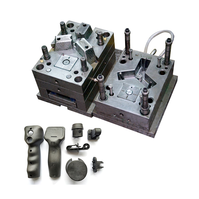
A mold must not simply produce a good part. It must produce it repeatedly, continuously, and within a profitable cycle time. T1 and T2 tryouts serve as the ultimate stress test. You must look past cosmetic perfection and demand rigorous process data.
Execute a progressive short-shot study. You should run the machine at 70%, 80%, and 90% fill volumes without holding pressure. You must verify all cavities fill simultaneously. Imbalances create massive quality control issues later. They lead to flash in some cavities and short shots in others.
Weigh the parts from each cavity during the short-shot phase. If cavity #1 weighs significantly more than cavity #8, your runner system is unbalanced. The manufacturer must correct the gate sizes or runner layout before proceeding.
Table 1: Short Shot Fill Balance Analysis
| Fill Percentage | Cavity 1 Weight (g) | Cavity 4 Weight (g) | Cavity 8 Weight (g) | Acceptance Criteria |
|---|---|---|---|---|
| 70% | 14.2 | 14.1 | 14.3 | < 2% variation |
| 80% | 16.5 | 16.4 | 16.6 | < 2% variation |
| 90% | 18.8 | 18.7 | 18.9 | < 1.5% variation |
Compare actual tryout cycle times against your originally quoted estimates. Extended cycle times destroy unit economics. If a supplier quoted a 15-second cycle but the tryout requires 22 seconds to prevent warping, your annual production capacity drops by nearly a third. You must hold the supplier accountable for the contracted cycle time.
Inspect the process for smooth ejection. Parts must fall freely without distortion, deep pin push marks, or dragging along the core. Ejector pins should leave minimal visual disruption on the plastic surface.
Crucially, verify operators used no manual intervention to achieve the tryout samples. Mold release sprays artificially mask draft angle issues and undercuts. If you see a technician spraying the tool, invalidate the tryout run immediately.
Tolerances do not scale linearly. When you build a tool with multiple cavities, the risk of dimensional deviation multiplies. Evaluating a high precision plastic injection mold for an automotive part or medical device requires strict, cavity-by-cavity statistical analysis. Guesswork has no place here.
Demand a comprehensive First Article Inspection (FAI) report. This document must cover 100% of the critical-to-quality (CTQ) dimensions. You need measurements for parts from every single cavity, not just a random sample. The report must clearly map every measured dimension back to the original CAD model. Look for out-of-tolerance trends isolating specific cavities.
Visual approval means nothing without statistical backing. Request a formal process capability study.
You must demand a demonstrated Cpk of 1.33 or higher across all cavities. A score of 1.33 proves the mold can ensure long-term dimensional stability without constant process tweaking by your technicians.
Never measure parts immediately out of the press. Measure post-shrinkage dimensions only after 24 to 48 hours of ambient cooling. Plastics relieve internal stress over time, often warping hours after ejection.
Inspect all parting lines, shut-offs, and lifter intersections for microscopic flash. Flash indicates inadequate clamping force, poorly fitted steel, or subpar machining tolerances. Even microscopic flash degrades tool life over time because the steel faces crash into each other during clamping.
Overseas procurement requires rigid, evidence-based verification. You must bridge the geographic trust gap when you cannot physically visit the facility. Accepting a tool blindly over email often results in receiving a compromised asset.
Do not accept highly edited, two-minute video clips of a mold running perfectly. Mandate unedited, continuous video feeds. Watch the mold run live for at least one to two hours. This proves the tool achieves thermal equilibrium and sustains continuous, automated operation. You must confirm operators do not need to pause the machine to clear stuck parts manually.
Request a high-definition video of the tool being broken down immediately post-tryout. You want to inspect the internal mechanisms after they endure thermal and mechanical stress.
For high-value projects, never rely solely on the factory’s internal quality control data. Stipulate the use of an independent, local inspection agency. Have them visit your multi-cavity injection mold supplier to verify dimensions, validate steel hardness, and supervise the tryout. This independent verification provides peace of mind before you authorize the final, non-refundable payment.
Moving from the evaluation phase to final sign-off requires a formal paper trail. You are transferring a highly engineered asset. Ensure you collect all intellectual property and maintenance data before the crate ships.
Suppliers frequently modify mold steel during tryouts to dial in dimensions. They grind gates, add weld spots, or adjust vents. You must collect updated 2D and 3D mold designs. Demand the "as-built" CAD files, not the initial design files. Secure the complete Bill of Materials (BOM) and preventative maintenance schedules.
High-volume molds consume wear items constantly. Confirm the supplier includes a robust spare parts package in the shipping crate. Your inventory should include extra ejector pins, custom O-rings, replacement heating coils, and return springs. Having these items on hand prevents weeks of downtime when a minor component fails.
Establish clear, binary criteria for your sign-off.
Approval Status Criteria
| Status Level | Definition | Action Required |
|---|---|---|
| Rejected | Fails critical dimensions; excessive flash; cycle time exceeded. | Supplier must rework steel and conduct new T-trials at their cost. |
| Conditional Approval | Meets CTQ specs; minor modifications needed (e.g., deeper vents, polishing). | Approve shipping, but withhold final 10% payment until factory validates fixes. |
| Full Approval | Meets all Cpk targets; automated cycle time verified; steel certified. | Sign final documents, release payment, and prepare for mass production. |
A: Typically, 100 to 300 continuous shots are required. This allows the multi-cavity injection mold to reach complete thermal equilibrium. It also provides enough physical samples to conduct a reliable statistical process capability analysis (Cpk).
A: For standard commercial parts, variation should remain less than 1% to 2%. For high-precision applications, variation must stay strictly under 0.5%. This ensures exceptional dimensional consistency and proves the runner system is perfectly balanced.
A: Unbalanced runners cause uneven pressure drops across the tool. Some cavities will overpack, resulting in flash or high internal stress. Simultaneously, other cavities will underfill, causing short shots. This imbalance drastically reduces your production yield rates.
A: You should receive final as-built CAD files, original material certificates, heat treatment reports, and FAI dimensional reports. Additionally, request injection molding parameter sheets showing the optimal process window, and a detailed recommended maintenance schedule.


