


Views: 0 Author: Site Editor Publish Time: 2026-09-06 Origin: Site


Mold performance loss goes beyond simple mechanical failure. It creates a compounding financial leak for manufacturers. You might notice cycle time creep, increased scrap rates, and unplanned downtime. These issues eat into profit margins daily. While all tooling experiences wear over time, premature degradation is rarely normal. It usually signals misaligned design specifications. Sometimes it points to improper resin handling. Often, it reveals a reliance on reactive maintenance rather than proactive care.
Recognizing these root causes helps you stop the bleeding. We will explore a practical framework for diagnosing current tooling failures. This guide establishes strict baseline criteria for your next procurement cycle. You will learn how to identify wear symptoms early. We will also cover how material selection prevents catastrophic breakdowns. By implementing these strategies, you can stabilize production and protect your tooling investments.
Cooling channels degrade silently over thousands of cycles. Water quality heavily influences this degradation. Minerals like calcium build up inside the cooling lines. This scale buildup acts as an insulator against the tool steel. It severely restricts thermal transfer during the injection process. When heat cannot escape efficiently, operators must compensate. They usually extend the cooling timer to prevent part warpage upon ejection. This adjustment causes cycle time creep. Adding just two seconds to a cycle destroys profit margins on high-volume runs. You must monitor cycle times constantly. If operators keep adding cooling time, your channels likely need descaling.
Clamp tonnage misalignment destroys parting lines rapidly. Excessive clamp force crushes the steel mating surfaces. Mechanical fatigue sets in along these critical edges. Conversely, insufficient clamp force allows the two halves to separate slightly during injection. High-pressure molten plastic escapes through these gaps. This escaping material creates flash on the finished parts. Flash requires manual trimming. Manual trimming increases labor costs and slows down delivery. Mechanical fatigue also causes the parting line to roll over time. Once the steel deforms, simple adjustments cannot fix the issue. You will need expensive welding and re-machining to restore the seal.
Cosmetic flaws usually indicate advanced mechanical wear. Draft angles lose their optimal geometry due to continuous friction. When draft angles wear down, parts stick inside the cavities. Ejection becomes harsh and unpredictable. This sticking causes deep drag marks along the sides of the product. Inadequate polishing routines accelerate this decline. Texture finishes fade into smooth, glossy patches. Ejector pins start leaving deep indentations on the part surface. These pin marks signal that the part is resisting release. Visual rejects escalate quickly when surface defects multiply. You must track cosmetic downgrades as early warning signs of tool fatigue.
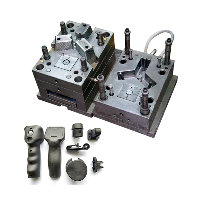
Resin additives wreak havoc on unprotected tool steel. Manufacturers add glass fibers to strengthen parts. These fibers act like microscopic sandpaper against the cavity walls. They strip away surface finishes rapidly. Flame retardants introduce a different threat. They often release corrosive gases during the heating phase. This chemical off-gassing attacks the steel aggressively. It causes localized pitting and rust. Producing a standard household plastic component often involves these harsh additives. Areas with poor venting suffer the most. Trapped gases condense on the metal, accelerating corrosion. You must specify corrosion-resistant steel if your resin produces aggressive off-gassing.
Injection molding subjects steel to extreme temperature swings. Molten plastic heats the cavity rapidly. Chilled water cools the steel seconds later. This continuous thermal cycling creates massive internal stress. The steel expands and contracts violently. Over time, the surface develops micro-cracks. Engineers call this phenomenon heat checking. These tiny fissures spread across the mold face like a spiderweb. They transfer directly onto the molded part as raised ridges. Heat checking eventually weakens the core blocks. Catastrophic cracking can follow if you ignore the early signs. Proper thermal management during design prevents this specific type of fatigue.
Moving parts inside the tool require precise synchronization. Sliders, lifters, and ejector pins endure immense friction. Improper lubrication breaks down this mechanical harmony. High operating temperatures burn off standard greases quickly. Metal rubs against metal. Galling occurs on the ejector pins. Galling is the physical transfer of metal between sliding surfaces. It causes pins to seize up inside their bores. Slider wear disrupts the timing of undercuts. When mechanical synchronization fails, the tool can crash. A tool crash destroys cavities and halts production completely. You must use high-temperature, non-migrating lubricants to protect these moving elements.
Upfront steel choices determine how long the tool survives. Entry-level P20 steel offers a cheaper starting point. It machines easily and handles low-volume runs well. However, P20 is relatively soft. It falls between 28 and 32 on the Rockwell C scale (HRC). It wears out quickly under continuous, high-volume production. Hardened H13 steel provides a robust alternative. It reaches 50 to 52 HRC after heat treatment. H13 resists abrasion and thermal fatigue exceptionally well. Stainless steel inserts offer premium corrosion resistance for aggressive resins. Getting your household plastic mold specifications right prevents premature rebuilding costs. High volumes demand harder steel.
Tooling Steel Comparison Matrix
| Steel Grade | Hardness (HRC) | Wear Resistance | Ideal Production Volume |
|---|---|---|---|
| P20 | 28 - 32 | Low | < 100,000 cycles |
| H13 | 50 - 52 | High | 1,000,000+ cycles |
| 420 Stainless | 48 - 50 | Medium-High (Anti-Corrosion) | 500,000+ cycles |
Legacy straight-line cooling cannot manage heat effectively in complex parts. Drilled cooling lines only travel in straight paths. They often miss thick wall sections and deep cores. These missed areas become thermal hot spots. Hot spots prolong cycle times and warp the plastic. Conformal cooling solves this geometrical limitation. Engineers use 3D metal printing to curve cooling channels. These channels wrap around the exact contours of the product. They pull heat away uniformly. This architecture prevents thermal fatigue on the steel. It also slashes cooling times dramatically. Modern consumer products require this level of thermal management.
Air must escape the cavity faster than the plastic enters it. If air gets trapped, it compresses violently. Compressed air superheats and burns the plastic edge. This is called diesel burning. It leaves black soot on the part and pits the steel. Venting precision requires exact engineering tolerances. Vents must be deep enough to allow gas escape. Yet, they must remain shallow enough to prevent molten plastic from flashing. Typical vent depths hover around 0.0005 to 0.001 inches. Maintaining this exact tolerance over millions of cycles demands hardened perimeter steel. Regular cleaning prevents these microscopic vents from clogging.
Evaluating quotes based solely on upfront cost is dangerous. The cheapest bid usually cuts corners on steel quality. It might skip crucial cooling channels to save machining time. These shortcuts guarantee higher maintenance expenses later. You will face premature performance loss and excessive downtime. The purchase price represents only a fraction of the actual expense. You must calculate the long-term financial impact. Include projected cycle times, scrap rates, and maintenance intervals in your evaluation. A tool that runs two seconds faster pays for its premium price quickly. Look beyond the initial invoice to secure reliable production.
A competent partner validates the design before cutting any metal. You must assess a household plastic mold supplier on their engineering rigor. Ask for their Moldflow analysis capabilities. Moldflow software simulates how the resin fills the cavity. It predicts sink marks, warpage, and weld lines. Design for Manufacturability (DFM) verification catches structural flaws early. The supplier should recommend draft angle adjustments and wall thickness changes. They must prove the tool can withstand the required clamp tonnage. Never approve a build without a comprehensive DFM report. Engineering validation prevents costly rework after the tool arrives.
Tight-tolerance components demand strict manufacturing criteria. Sourcing a high precision plastic injection mold for items like airtight food containers is complex. These parts require perfect dimensional stability to function properly. You need verifiable Quality Assurance (QA) documentation from the builder. Demand Coordinate Measuring Machine (CMM) inspection reports for the core and cavity blocks. The builder must prove they hit the required steel tolerances. Ask about their machining equipment. High-speed CNC machines and precise EDM equipment are non-negotiable. Look for guarantees regarding dimensional stability over the first 100,000 cycles. Precision requires documented proof, not just marketing promises.
You cannot identify performance loss without a starting reference. You must document exact parameters on Day 1 of production. Record the optimized cycle time. Log the peak injection pressure and hold pressure. Weigh the finished part to establish a baseline mass. Measure the cooling water flow rate and temperature. These metrics form the DNA of a healthy household plastic mold. When operators need more pressure to fill the cavity later, you have data. When cycle times creep up, you can compare them to Day 1. Baseline metrics turn subjective complaints into objective diagnostic data.
Reactive repairs destroy production schedules. You must structure a rigid preventative maintenance protocol.
This structured approach catches minor wear before it causes major failures.
Every tool reaches a point of diminishing returns. You need financial frameworks for deciding when a degraded tool is dead. Welding damages the surrounding steel structure. Re-machining alters the original cavity dimensions slightly. A common industry threshold is the 30% rule. If the repair cost exceeds 30% of a new build, consider replacing it. Track the frequency of unplanned stops. If a tool breaks down three times in a single month, its reliability is gone. Continuing to patch a dying tool inflates your scrap rate. Set strict limits on repair budgets to justify timely replacements.
Procurement and engineering teams should audit their current tooling pain points immediately. Gather data on scrap rates, cycle time delays, and repair invoices. Use this historical data to draft stricter requirements for your next project. Demand DFM reports, Moldflow analysis, and harder steel grades in your future RFQs. Proactive standards secure long-term profitability.
A: It depends heavily on the SPI mold classification. An SPI Class 101 mold, built with hardened H13 steel, should exceed 1 million cycles with proper care. Lower-tier Class 103 molds (P20 steel) typically show wear around 250,000 cycles. Maintenance discipline heavily dictates the actual lifespan.
A: No. Coatings like Titanium Nitride (TiN) or Nickel-Teflon delay initial wear and improve release. However, they cannot fix underlying mechanical fatigue, crushed parting lines, or poor cooling design. Coatings are preventative enhancements, not restorative cures for degraded steel.
A: Early flash usually points to insufficient clamp tonnage on the injection machine or severe parting line misalignment. It can also stem from unexpected resin viscosity changes or using soft tooling steel that deformed under high injection pressure. Immediate realignment and parameter checks are required.


