


Views: 0 Author: Site Editor Publish Time: 2026-10-01 Origin: Site


Replacing metal components with glass-filled polymers requires absolute precision during the engineering and manufacturing phases. Polyamide 66 reinforced with 30% glass fiber offers exceptional mechanical strength. It also delivers outstanding thermal resistance for demanding industrial applications. However, this advanced material poses significant processing risks if mishandled on the production floor.
The primary barriers to scaling production effectively are anisotropic shrinkage, severe warpage, and accelerated tool wear. Miscalculating these critical variables during the initial evaluation stage often leads to costly mold reworks. Consequently, manufacturing teams face delayed time-to-market and compromised part performance.
This guide breaks down the essential design for manufacturability (DFM) factors you must address. We explore proven shrinkage mitigation strategies alongside robust tooling considerations. You will learn the specific evaluation criteria required to successfully source and manufacture highly reliable components.
Selecting the right polymer often dictates the entire trajectory of a manufacturing project. When engineers choose PA66 GF30 injection molding, they typically aim to replace heavy metal components without sacrificing structural integrity. Understanding how material properties translate into real-world outcomes ensures you apply this resin where it performs best.
You can directly link the inherent properties of PA66 GF30 to specific engineering outcomes. The material behaves predictably under extreme stress, making it highly valuable for complex assemblies.
Transitioning from metal to plastic requires a thorough financial and functional analysis. Engineers must assess the return on investment (ROI) of using PA66 GF30 compared to die-cast aluminum or standard non-reinforced nylons. While aluminum offers excellent strength, it requires extensive post-machining operations. Conversely, injection molding delivers net-shape parts directly from the press.
Lighter part weights significantly reduce downstream shipping expenses. Furthermore, lighter components require less energy to operate within moving assemblies, creating distinct operational advantages. These logistical and functional savings effectively offset the initial upfront investments required for hardened steel molds.
Modern electrical and automotive applications mandate strict regulatory adherence. You must validate your material choices against global safety standards before approving the tooling budget. Verify the specific UL94 flammability ratings of your chosen resin grade, as some PA66 GF30 blends include flame retardants. Additionally, ensure the material supplier provides RoHS compliance documentation to avoid regulatory bottlenecks during international distribution.
Shrinkage remains the most unpredictable variable when processing glass-reinforced polymers. Unlike unfilled plastics, which shrink uniformly as they cool, glass-filled nylons exhibit complex thermal behaviors. We must aggressively manage these behaviors during the mold design phase.
The core challenge lies in the orientation of the glass fibers during the injection phase. As molten plastic shoots into the cavity, the rigid glass fibers align parallel to the flow direction. This alignment physically restricts the polymer matrix from contracting naturally as it solidifies.
In the flow direction, shrinkage is minimal. It typically hovers between 0.2% and 0.4%. However, in the transverse direction (perpendicular to the flow), the fibers offer no resistance. The polymer matrix shrinks normally, often experiencing contraction rates between 0.7% and 1.2%. This differential shrinkage causes severe internal stress, which ultimately manifests as part warpage.
Material Shrinkage Behavior Chart
| Direction of Measurement | Typical Shrinkage Rate | Primary Cause | Impact on Final Part |
|---|---|---|---|
| Flow Direction (Parallel) | 0.2% – 0.4% | Glass fibers physically restrict polymer contraction. | High dimensional stability along the flow path. |
| Transverse Direction (Perpendicular) | 0.7% – 1.2% | Lack of fiber reinforcement along this axis allows normal polymer shrinkage. | Increased risk of bowing and dimensional variance. |
You cannot eliminate anisotropic shrinkage, but you can control it through rigorous engineering. Strategic mold design forces the material to behave predictably.
Gate placement dictates the flow path and, consequently, the fiber orientation. We utilize multi-point gating or edge gates to distribute the melt evenly. This approach intentionally scatters the fiber alignment in wide sections, minimizing uneven contraction.
Furthermore, mold cooling optimization directly combats warpage. Uneven mold temperatures create uneven cooling rates, locking internal stresses into the part. Designing conformal cooling channels ensures uniform temperature distribution across complex geometries. This technique rapidly pulls heat away from thick sections, mitigating warp-inducing stresses before ejection.
Engineers often make the mistake of applying standard metal tolerances to injection-molded plastics. You must set realistic geometric dimensioning and tolerancing (GD&T) expectations prior to cutting the tool. Discuss achievable flatness and concentricity metrics with your molding partner, taking the differential shrinkage rates into account.
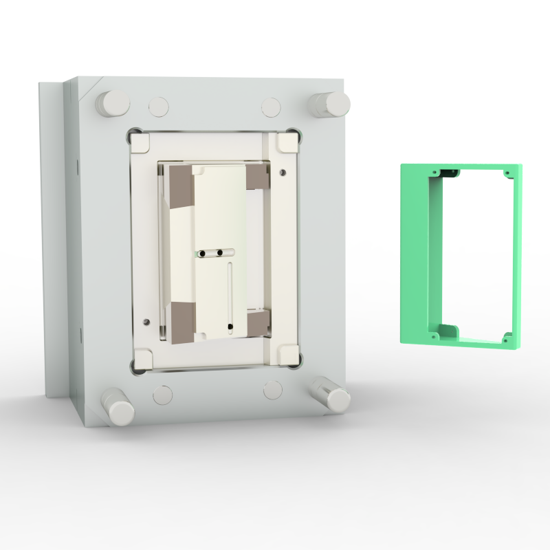
A successful mold relies entirely on a flawless part design. By adhering to strict design rules for PA66 GF30 plastic parts, you eliminate most manufacturing defects before steel is even ordered.
Maintaining a uniform wall thickness is paramount. We recommend designing walls between 1.5mm and 3.0mm thick. Uniform walls ensure that the plastic cools at a consistent rate throughout the cavity. This consistency actively prevents sink marks and internal voids.
When varying thickness is unavoidable, you must use gradual transitions. Abrupt changes in thickness disrupt the melt flow and cause turbulence, which misaligns the glass fibers. Instead, core out thick sections to maintain structural integrity without accumulating unnecessary mass.
Glass-filled nylon is exceptionally rigid once cooled. It will not flex or yield easily during the ejection sequence. Therefore, you must specify minimum draft angles of 1° to 1.5° on all vertical walls. If the part requires a textured surface finish, increase the draft angle by an additional 1.5° per 0.025mm of texture depth. Proper draft prevents severe ejection drag marks and protects the mold surface.
Weld lines represent the most significant structural vulnerability in any reinforced polymer.
Never include sharp internal corners in a PA66 GF30 design. Sharp corners act as severe stress concentrators. When subjected to mechanical loads, crack propagation almost always begins at these sharp intersections. We require a minimum radius of 25% to 60% of the nominal wall thickness. Adding generous fillets strengthens the part and allows the highly viscous glass-filled melt to flow smoothly around corners.
The manufacturing environment dictates the final quality of the product. Even a perfectly designed part will fail if the molder cuts corners on tooling quality or process controls. Executing robust PA66 GF30 injection molding requires specialized equipment and stringent handling procedures.
Standard tooling approaches do not work here.
Polyamide 66 is a highly hygroscopic material, meaning it naturally absorbs moisture from the surrounding air. You must reduce the resin's moisture content to below 0.2% prior to molding.
Failure to dry the resin properly yields disastrous results. As the wet plastic enters the heated barrel, the trapped water instantly vaporizes. This steam creates cosmetic defects known as splay, appearing as silver streaks on the part surface. More dangerously, the steam induces a chemical reaction called hydrolysis. Hydrolysis physically breaks down the polymer chains, resulting in a catastrophic loss of mechanical strength that you cannot detect visually.
Thermal management of the tool directly influences the cosmetic appearance of the final part. Molders must maintain high mold temperatures, typically between 80°C and 120°C.
A hot mold allows the polymer matrix to remain fluid just long enough to flow over and encapsulate the glass fibers against the cavity wall. If the mold runs too cold, the plastic freezes instantly. This prevents encapsulation and leaves exposed glass fibers protruding from the surface. We refer to this defect as "floating fibers," and it results in a rough, frosty, and cosmetically unacceptable finish.
You cannot trust a challenging resin to an unverified manufacturer. Evaluating potential partners requires digging past marketing brochures and interrogating their engineering processes. A competent molder operates with transparency, relying on empirical data rather than guesswork.
When auditing a potential manufacturing partner, evaluate them across three specific operational dimensions:
Once you identify a promising vendor, take concrete steps to validate their expertise. First, require a detailed DFM report focused specifically on warp analysis and gate location strategy. This document will reveal their understanding of anisotropic shrinkage.
Next, request physical samples of previous glass-filled nylon parts they have manufactured. Inspect these samples closely. Look for rough surface finishes (floating fibers), flash, or dimensional inconsistencies. If their sample parts pass inspection, you can confidently proceed to the quoting phase.
PA66 GF30 injection molding offers unmatched structural benefits for the most demanding engineering applications. However, success is never guaranteed. Engineers must rigorously account for anisotropic shrinkage, mitigate weld line vulnerabilities, and design specifically for the material's rigid nature. Furthermore, the manufacturing floor must maintain strict control over resin moisture and mold temperatures.
Transitioning safely from prototyping to high-volume production requires a manufacturing partner who leads with data. Rely on comprehensive Moldflow analysis and demand stringent, hardened tooling standards to protect your investment.
Take action today to secure your project's success. Submit your CAD files for a comprehensive DFM review. Our engineering team will identify potential warpage risks, optimize your wall thicknesses, and secure a highly accurate tooling quote tailored to your specific performance requirements.
A: Because of the glass fibers, shrinkage is highly anisotropic. It typically ranges from 0.2% to 0.4% in the direction of flow, and 0.7% to 1.2% in the transverse direction.
A: This is known as "floating fiber" or glass exposure. It usually occurs when the mold temperature is too low or the injection speed is too slow, preventing the polymer matrix from fully encapsulating the glass fibers at the surface.
A: No, unless it is for a very short prototype run (under a few thousand parts). For production volumes, the abrasive nature of 30% glass fiber requires hardened steels like H13 or S136 to prevent rapid gate and cavity wear.
A: If not dried to below 0.2% moisture content, water vaporizes during the melt phase. This causes cosmetic defects (splay) and induces a chemical breakdown (hydrolysis) that severely compromises the part's final tensile strength.


