


Views: 0 Author: Site Editor Publish Time: 2026-08-20 Origin: Site


Industrial equipment demands components built to survive exceptionally harsh environments. These parts face repetitive mechanical stress, extreme temperatures, and strict regulatory standards daily. Relying on generic design approaches often causes premature part failure. This misstep inevitably leads to highly expensive tooling rework.
Moving from initial prototyping or CNC machining to scaled production represents a significant leap. It requires precise specification of materials. You must also establish tight dimensional tolerances and rigorous quality controls at every step.
This guide outlines an evidence-based framework for specifying custom plastic injection parts reliably. We ensure your core engineering requirements align perfectly with major tooling investments. You will learn exactly how to guarantee robust final part performance before anyone starts cutting mold steel.
Define Environmental Stressors First: Material selection must precede final part design, as shrinkage rates and thermal limits vary drastically among engineering-grade resins.
Prioritize DFM to Protect Tooling ROI: Minor geometry adjustments (draft angles, uniform wall thickness) prevent costly mold modifications and reduce cycle times.
Match Tooling Strategy to Volume: Align mold materials (aluminum vs. hardened steel) with expected production life cycles to optimize upfront capital expenditure.
Demand Data-Driven Validation: Vet manufacturing partners based on their ability to provide Moldflow analysis, First Article Inspection (FAI), and verifiable process capability (Cpk) data.
You must map out environmental stressors before drafting any CAD files. Document continuous operational temperature ranges clearly. Peak thermal exposure dictates polymer degradation limits over time. Furthermore, specify potential UV exposure or chemical contact. Solvents, heavy industrial lubricants, and aggressive cleaning agents break down weaker polymers rapidly. Identifying these factors early prevents catastrophic field failures.
Designers must distinguish between different mechanical load requirements. Assess whether the part handles static load bearing or dynamic forces. Does it require high impact resistance? Continuous fatigue from constant vibration demands highly durable resins. We often see engineers overlook polymer creep. Creep occurs when plastics deform under prolonged, steady stress. Documenting load types ensures you select a structurally sound material.
Regulatory compliance frames your entire manufacturing project. Identify all necessary industry certifications upfront. UL94 flammability ratings remain mandatory for electrical and heavy equipment housings. RoHS and REACH compliance directly affect material availability, especially in European markets. Specific ISO requirements govern medical, automotive, and aerospace components. Establishing these benchmarks early prevents costly redesigns later.
Conduct a thorough risk assessment for the component. Define the direct operational cost of part failure. Unplanned machine downtime and severe safety hazards justify higher upfront tooling investments. Choosing premium engineering materials pays off when field failures pose significant risks. Tighter inspection tolerances also mitigate disaster. Evaluate these consequences carefully to justify your engineering budget.
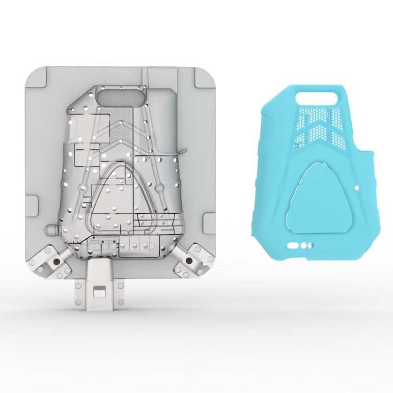
Industrial applications usually bypass commodity plastics like standard PP or ABS. Instead, they strongly favor engineered polymers. These include Glass-filled Nylon, POM (Delrin), Polycarbonate, and PEEK. We use these engineering resins for their superior mechanical stability. They handle extreme heat and aggressive chemical environments easily. Commodity resins simply deform or degrade under similar industrial stress.
Additives and fillers change material behaviors entirely. You might add glass or carbon fibers to a base resin. They drastically increase overall tensile strength. However, they also introduce significant manufacturing tradeoffs. Fiber-filled materials increase potential part warpage during cooling. They also cause rapid mold wear due to their highly abrasive nature. You must balance strength against mold longevity.
Consider shrinkage and mold compatibility very carefully. Switching materials after cutting the mold is rarely viable. Different engineering resins have highly distinct shrink rates. If you design a mold for ABS, injecting Nylon yields undersized parts. The cavity dimensions will not match the new polymer's behavior. Always finalize your material selection before approving the final tool design.
Factor in supply chain realities from day one. Assess raw resin availability before finalizing your engineering specs. Highly specialized custom colors often face long lead times. Custom-blended resins usually require large minimum order quantities (MOQs). This heavily impacts your inventory management strategy. Standard engineering resins offer much better supply chain flexibility.
Resin Type | Average Shrink Rate | Key Industrial Benefit | Common Drawback |
|---|---|---|---|
Standard ABS | 0.4% - 0.8% | High impact resistance, cheap | Poor chemical resistance |
Nylon 6/6 (Glass-Filled) | 0.2% - 0.6% | Extreme tensile strength | Highly abrasive to mold steel |
POM (Delrin) | 1.8% - 2.2% | Low friction, high wear resistance | Difficult to mold without voids |
Polycarbonate (PC) | 0.5% - 0.7% | High heat resistance, transparent | Prone to stress cracking |
Uniform wall thickness actively maintains structural integrity. It prevents severe sink marks and mitigates internal warping. Avoid thickening entire walls to add strength. Instead, use proper ribbing and strategic gussets. They add necessary rigidity without increasing cycle cooling times. Maintaining a consistent wall thickness represents the golden rule of specifying injection molded parts successfully.
Specify adequate draft angles to ensure smooth ejection. We recommend a 1° to 3° minimum draft on all vertical walls. Heavily textured industrial finishes require even more draft angle clearance. Proper angles prevent part damage during the ejection phase. They eliminate scuff marks and reduce stress on the mold ejector pins.
Reduce tooling complexity by simplifying your coring and undercuts. Design out the need for mechanical side-actions where possible. Avoid complex lifters or collapsible cores unless absolutely necessary. Complex mold mechanics drastically increase upfront tooling expenses. They also demand more frequent preventative maintenance. Simplifying the geometry protects your initial capital investment.
Understand tolerance realities to avoid over-tolerancing parts. Specify critical-to-function (CTF) dimensions very clearly. Accept standard commercial tolerances for non-mating surfaces. Adhering to standards like DIN 16901 keeps production economical. Unnecessarily tight tolerances demand excessive process controls. They drive up cost premiums without adding any functional value to the equipment.
Assess exactly when to transition from prototyping to scaled production. Moving from 3D printing or CNC machining requires a robust strategy. Prototypes prove the concept, but injection molding proves the manufacturing viability. Do not rush into cutting expensive steel. Use bridge tooling to validate your geometry before committing to high-cavitation production molds.
Select mold materials based firmly on SPI classifications. Aligning steel types with your volume expectations optimizes upfront capital expenditure.
Class 105/104 (Aluminum/Soft Tooling): Best suited for low-volume runs or bridge tooling. Aluminum cuts fast but wears out quickly. It supports highly iterative designs perfectly.
Class 103/102 (Pre-hardened Steel - P20): The industry standard for medium-volume production. P20 steel reliably handles 10,000 to 100,000 parts without significant wear.
Class 101 (Hardened Steel - H13): Strictly required for high-volume, multi-year runs. You also need hardened steel for highly abrasive materials like glass-filled plastics.
Evaluate cavitation economics based purely on projected volume. A single-cavity mold offers a much lower upfront cost. However, it yields a notably higher piece price. Conversely, multi-cavity or family molds demand high upfront capital. They provide the lowest unit price at scale. Balance your initial budget against your long-term production forecasting.
Clarify ownership and maintenance terms early in the negotiation. Establish strict mold ownership contracts clearly. Define routine preventative maintenance schedules before signing any agreements. Ensure the supplier explicitly guarantees the mold's shot-life. Proper maintenance prevents flash, dimensional drift, and unexpected tooling breakdowns during critical production runs.
Strong engineering support sets top-tier suppliers apart. Look for partners providing proactive DFM feedback immediately. They should supply detailed Moldflow analysis during the quoting phase. Avoid suppliers who blindly quote "as-is" CAD files. Good partners anticipate flow lines, weld marks, and cooling inefficiencies before they happen.
Verify their internal equipment capabilities thoroughly. Ensure the facility's press tonnage aligns with your part size and projected area. Tonnage requirements vary drastically across industrial components. You might need a 50-ton press for micro components. Conversely, large equipment housings often demand 1,000-ton presses or larger. Undersized presses cause incomplete fills and flashing.
Demand strict quality assurance and raw material traceability. Require documented processes and an active ISO 9001:2015 certification. Request thorough First Article Inspection (FAI) reports for every new tool. Ensure they maintain raw material lot traceability for strict accountability. Verifiable process capability (Cpk) data proves they can maintain dimensions over long runs.
Watch out for critical supplier red flags. Apply skeptical evaluation criteria during your facility audits. Beware of manufacturers lacking dedicated in-house tooling maintenance. Unusually low tooling quotes often mask poor mold steel quality. Avoid suppliers resisting transparent quality reporting. A secretive manufacturer often hides poor process controls and high internal scrap rates.
Lock down your material requirements and environmental stressors before finalizing your CAD designs.
Apply Design for Manufacturability (DFM) principles rigorously to avoid expensive mold modifications later.
Match your tooling investment directly to your expected lifecycle volume using correct SPI classifications.
Before requesting quotes, finalize your Critical-to-Quality (CTQ) dimensions and clearly identify necessary compliance standards.
Request a comprehensive DFM review and Moldflow analysis from your shortlisted manufacturing partners.
A: Minimum order quantities vary widely based on your manufacturer and tooling type. Prototyping or on-demand facilities may offer MOQs as low as 100 units. These suppliers cater to iterative testing. Conversely, traditional industrial suppliers typically require orders of 5,000 units or more. They need these larger volumes to offset high setup and machine calibration costs.
A: Tooling timelines depend heavily on your chosen mold material. Facilities can cut soft aluminum tooling in just one to three weeks. In contrast, hardened steel production molds generally require four to eight weeks for fabrication. You must also add extra time for initial T1 sampling. Expect further delays if the design requires subsequent mold revisions.
A: Generally, you cannot swap materials freely in the same mold. Different engineering resins possess highly distinct shrink rates. A mold cut specifically for ABS will produce severe dimensional flaws if injected with Nylon. Nylon acts as a high-shrink material. Your resulting parts will emerge undersized or warped. Always lock down material selection before finalizing mold geometry.
A: Commercial tolerances easily accommodate natural process variations. They allow manufacturers to produce parts faster and cheaper. Precision tolerances demand strictly controlled molding parameters. These tighter dimensions often require ±0.002 inches of accuracy. Achieving this requires premium tooling and extensive quality monitoring. It inherently generates higher scrap rates. Ultimately, precision tolerances drive up final part costs substantially.


