


Views: 0 Author: Site Editor Publish Time: 2026-09-10 Origin: Site


Securing reliable industrial injection molded parts requires moving past baseline piece-price comparisons. We must evaluate structural integrity, material suitability, and long-term production scalability. OEMs and engineers face high stakes at the decision stage. Tooling investments represent significant capital outlays. Failure to validate part quality early leads to costly downstream defects. You risk serious project delays if you skip proper evaluation steps.
A rigorous comparison relies on a structured evaluation. You need to assess material properties, process controls, and quality assurance data. Choosing capable manufacturing partners ensures consistent and repeatable success. This guide will walk you through setting specifications, selecting materials, and verifying tool viability. You will learn how to navigate physical testing and vet potential manufacturing partners thoroughly.
Defining functional success criteria means moving beyond basic dimensions. You must identify load-bearing requirements for your components. Thermal resistance and chemical exposure limits also dictate project success. Setting verifiable industrial injection molded parts specifications early prevents scope creep. Engineering teams should document expected environmental stressors. We map these stressors directly to our baseline part geometry.
Tightening tolerances unnecessarily drives up tooling and production costs. You must differentiate between critical-to-function (CTF) dimensions and nominal dimensions. High precision requires slower cycle times. It demands premium steel and frequent mold maintenance. Standardize your nominal dimensions where possible to save resources. A common mistake is applying blanket tight tolerances across the entire CAD model. This inflates quotes and complicates quality control.
First Article Inspection (FAI) plays a vital role in production validation. Buyers must demand comprehensive FAI reports. These reports verify initial samples match engineered blueprints perfectly. You should never approve full production runs without FAI clearance. A meticulous FAI prevents mass-producing defective units. Review the ballooned drawing alongside the physical inspection data. This ensures every single feature falls within acceptable deviation ranges.
Choosing resins for custom plastic injection parts for industrial applications requires deep analysis. You often compare commodity plastics like PP and PE against engineering resins. High-performance polymers like PEEK and Polycarbonate offer superior yield strength. They withstand extreme environmental conditions better. You must weigh the raw material cost against mechanical performance requirements.
Application-specific compliance shapes material choices significantly. For any automotive part, you must evaluate UV stability and impact resistance. Lightweighting potential often demands glass-filled nylons or carbon-fiber composites. In medical and regulated sectors, biocompatibility matters most. You must verify ISO 10993 compliance and FDA-grade resin traceability. Every material lot requires strict certification tracking.
Material selection also dictates shrinkage and warpage risks. These factors influence mold design directly. They alter cooling times and gate placements. You need transparent assumptions from your manufacturing partners regarding shrink rates. Semi-crystalline materials shrink differently than amorphous materials. Accounting for anisotropic shrinkage prevents severe part deformation post-molding.
| Material Category | Polymer Example | Key Strength | Common Application |
|---|---|---|---|
| Commodity Thermoplastic | Polypropylene (PP) | High chemical resistance and flexibility | Living hinges, consumer packaging |
| Engineering Thermoplastic | Polycarbonate (PC) | Extreme impact resistance and clarity | Machine guards, automotive lenses |
| High-Performance Resin | PEEK | Exceptional thermal and mechanical strength | Aerospace components, medical implants |
| Composite Material | Glass-Filled Nylon | High rigidity and dimensional stability | Under-hood automotive brackets |
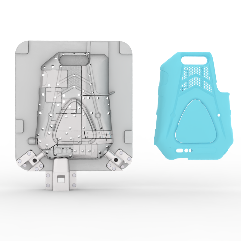
Standard injection molding works for many industrial components. However, specialized processes solve complex geometry challenges. You might specify overmolding or insert molding for enhanced grip. Multi-material requirements often demand these advanced techniques. Reaction Injection Molding (RIM) handles large, lightweight parts excellently. Evaluating the specific process ensures you optimize cycle times and material usage.
Tooling grade directly impacts longevity and part consistency. We compare SPI mold classifications ranging from Class 101 to Class 105. Steel hardness must align with projected production volumes. P20 steel suits medium runs well. H13 steel withstands high-volume, abrasive production demands. Evaluating steel types prevents premature tool wear.
Understanding SPI Tooling Classifications:
Cavitation strategy requires careful assessment before cutting steel. Single-cavity prototypes minimize initial capital risk. Multi-cavity or family molds boost high-volume efficiency dramatically. However, you must factor in dimension variations across different cavities. Balancing cavity count ensures consistent part quality. A poorly balanced multi-cavity tool leads to short shots in outer cavities.
Interpreting Moldflow analysis prevents catastrophic tooling mistakes. Predictive data reveals optimal gate placement across the geometry. It highlights potential knit lines and projected cooling rates. Accurate simulations guide design corrections before cutting steel. We use this digital validation to minimize physical trial-and-error.
You must identify red flags in early physical samples. Differentiating between cosmetic blemishes and structural defects remains critical. A cosmetic scratch might not fail a part. However, internal voids compromise load-bearing capacities immediately. You must establish visual quality standards early.
Common physical defects to monitor during validation:
Testing and validation confirm structural integrity accurately. You should implement destructive testing and stress testing protocols. Coordinate measuring machine (CMM) verification ensures physical parts match digital simulations. Real-world performance must mirror engineering expectations. Relying on advanced metrology eliminates guesswork from your quality assurance process.
Selecting an industrial injection molded parts supplier demands rigorous facility auditing. You must demand proof of active industry certifications. Quality management systems rely on strict ISO 9001 adherence. IATF 16949 ensures repeatable process controls specifically for automotive sectors. ISO 13485 covers stringent medical production standards. Verifying these credentials confirms baseline operational maturity.
Evaluate process capability and production capacity thoroughly. A supplier must demonstrate consistent machine calibration and maintenance schedules. Ask for historical defect tracking data on similar materials. Strong manufacturers utilize statistical process control (SPC) to monitor variables dynamically. They track injection pressure, mold temperature, and cooling times continually. This minimizes part-to-part variation.
Communication and engineering support indicate a supplier's true value. Assess their Design for Manufacturability (DFM) feedback carefully. A trustworthy partner pushes back on flawed designs. They never blindly cut steel just to secure a purchase order. Collaboration mitigates risk and improves final part quality. A comprehensive DFM report highlights draft angle issues and wall thickness inconsistencies upfront.
Comparing parts remains an exercise in continuous risk mitigation. You must balance material science capabilities and precise tooling strategies. Rigorous quality validation ensures long-term manufacturing success. Navigating these complexities requires a structured, data-driven approach.
Base your final decisions entirely on empirical data. Rely on DFM reports and comprehensive FAI physical samples rather than marketing claims. Validate material properties and process controls before committing to mass production. Real-world testing always outweighs theoretical assumptions.
Request a comprehensive DFM review from your engineering partners today. Submit your CAD files to secure a transparent tooling quote. Audit your prospective supplier's facility to ensure complete alignment with your quality standards.
A: Standard commercial tolerances typically sit around ±0.005 inches per inch. Precision or fine tolerances can achieve ±0.001 to ±0.002 inches. Material shrinkage heavily affects these numbers. Engineering resins with glass fillers hold tighter tolerances than highly shrinkable commodity plastics like polyethylene.
A: Injection molding creates discrete, 3D complex parts like enclosures or structural brackets. It utilizes a closed mold cavity. Extrusion strictly produces continuous 2D profiles like pipes, tubing, or weatherstripping by pushing melted plastic through a die. Choose your process based on part geometry.
A: An automotive quote must include PPAP (Production Part Approval Process) level requirements. Look for specialized material certifications proving UV and impact resistance. Ensure the quote outlines clear lifecycle tooling guarantees and specifies IATF 16949 quality compliance standards for repeatable production.
A: The standard timeline usually begins with a DFM review lasting 1-2 weeks. Tooling fabrication requires 4-8 weeks, depending on mold complexity and cavitation. FAI validation takes an additional 1-2 weeks. Once FAI samples are approved, mass production scales immediately.


